Engineering and Design Services
Solutions delivered, not just hours billed
Precision Engineering solutions for Machine Design, Lab Device Development, and Product Development.
Providing Useful solutions for clients who design, product, manufacture, service, or support technical products.

What Differentiates AMD&E Engineering Services?
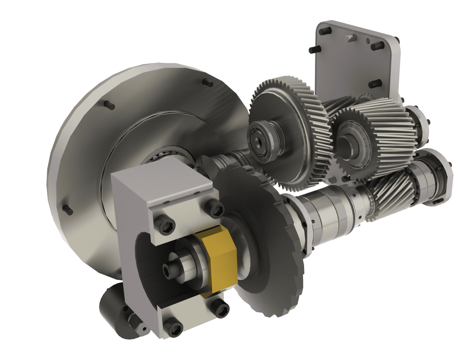
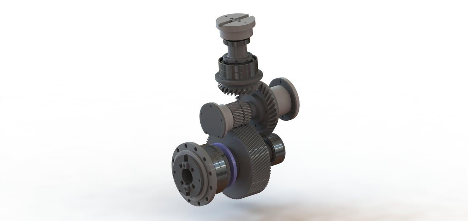
Design Engineering
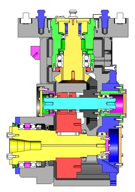
Design Engineering is where the rubber hits the road. It's the bridge between theory and practice. It's what sets us apart. Our team of engineers can break down difficult concepts and design a solution. Our design engineers understand the governing equations (first principles is the trendy description). But more importantly, they understand practical implementation. We use geometry, CAD, UX/UI, and system modeling. Our team is skilled in DFM, DFA, and manufacturing technologies. We use all of this to generate CAD Assemblies and Detail drawings that serve as the foundation for great solutions.
Solutions. Not just hours
AMD&E provides precision engineering solutions across machine design, laboratory device development, and full product development. We work with teams that build and support advanced technical products, bringing hands-on experience from concept through production. Our work is driven by results, not billable hours. Success is measured by finished products delivered on time, built right the first time, and equipped with the features users actually need. When experience matters and results are not optional, AMD&E is the engineering partner that delivers.

Customer Inspired, User Driven
At AMD&E, we listen closely to our clients and design with the end user in mind. Every solution is driven by real needs, not assumptions, with a focus on creating tools and systems that are practical, effective, and valuable in the field. By combining strong engineering fundamentals with modern technology, we move quickly to deliver solutions that are efficient, innovative, and cost‑effective.

Large or Small Projects | Big Results
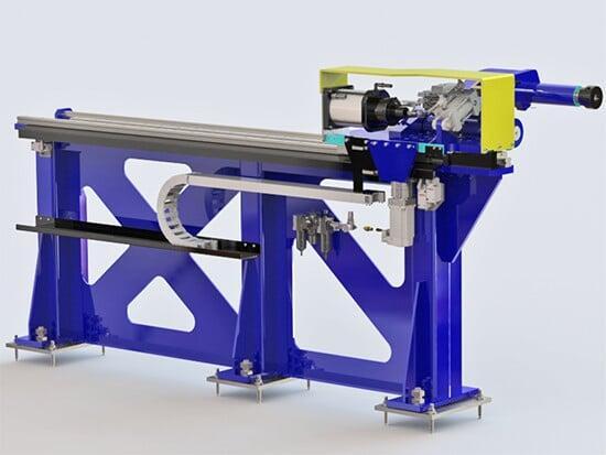
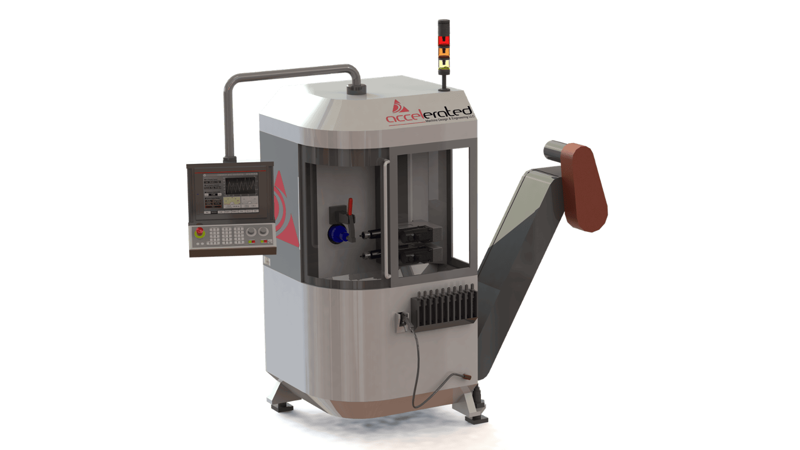
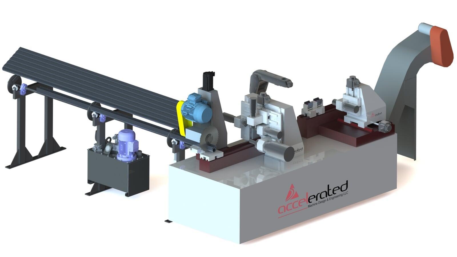
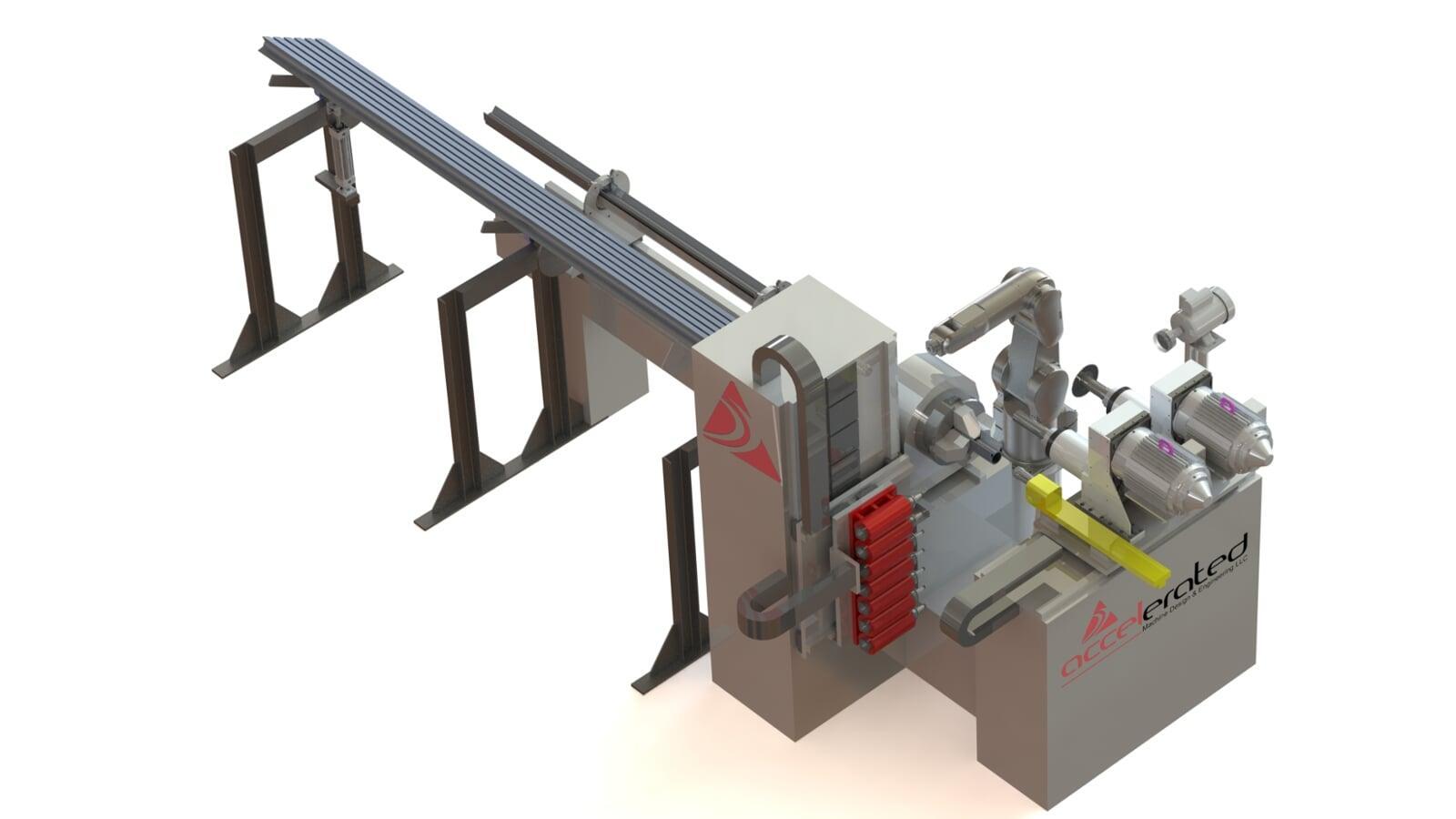
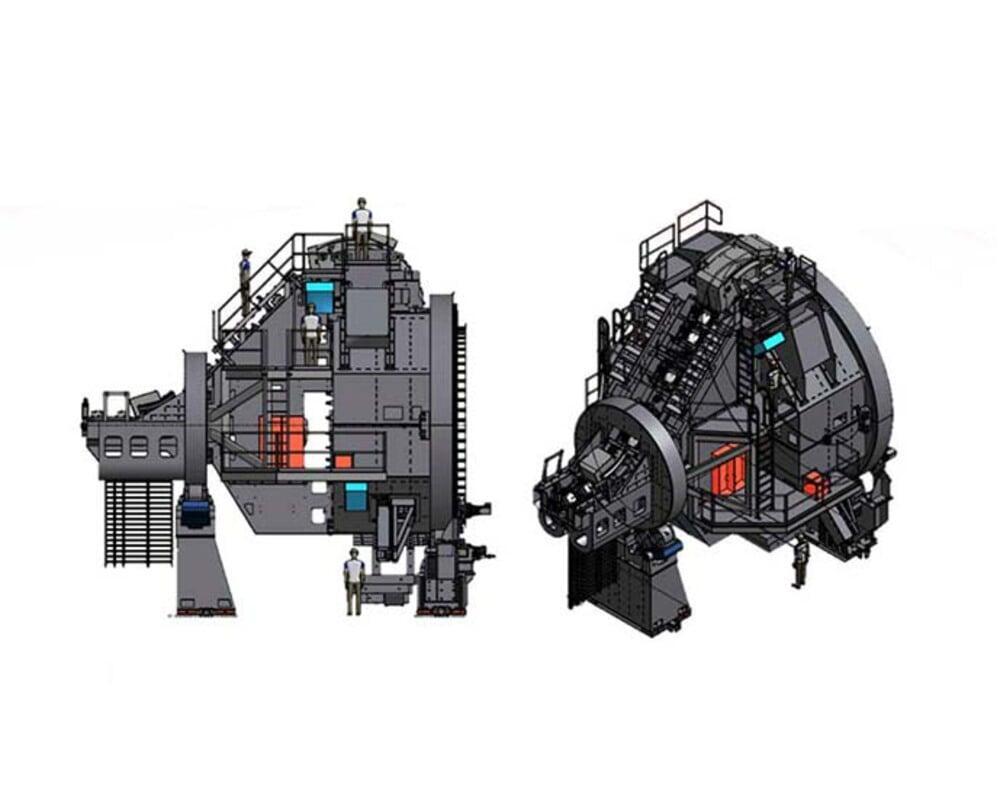
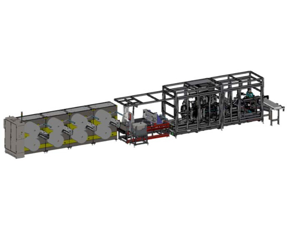
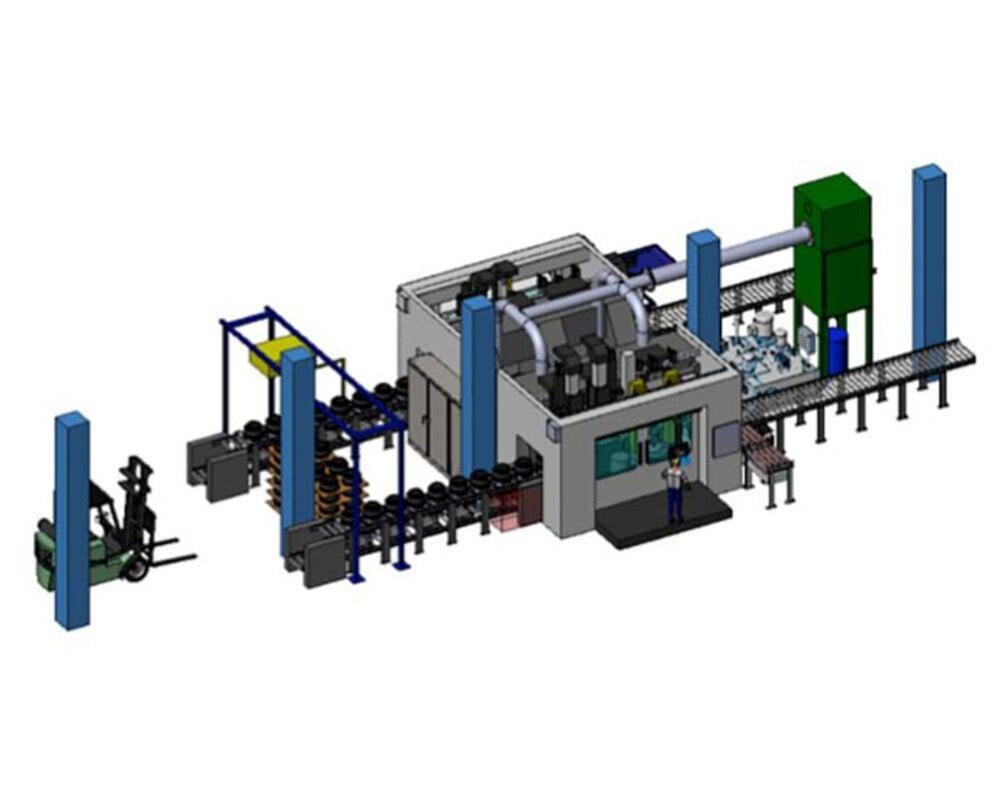
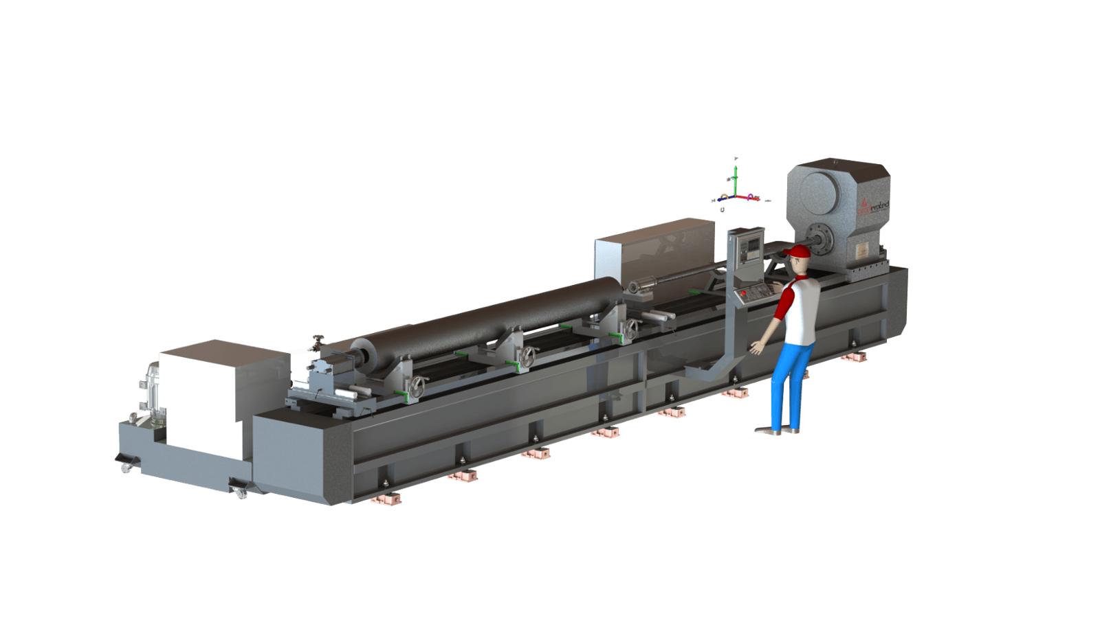
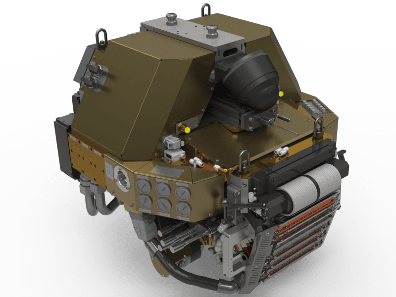
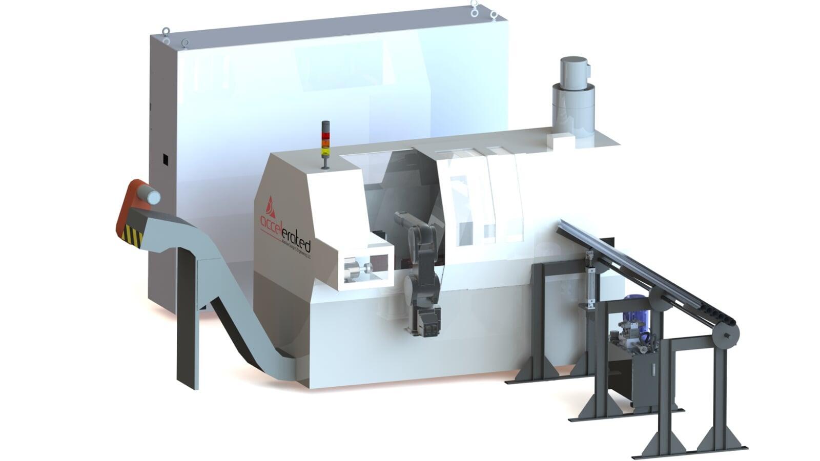
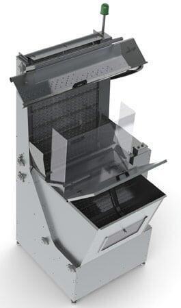
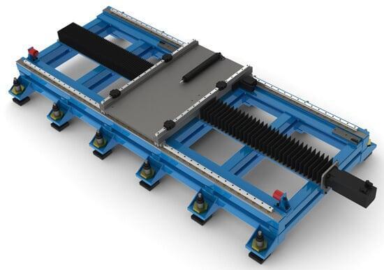
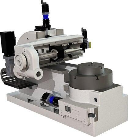
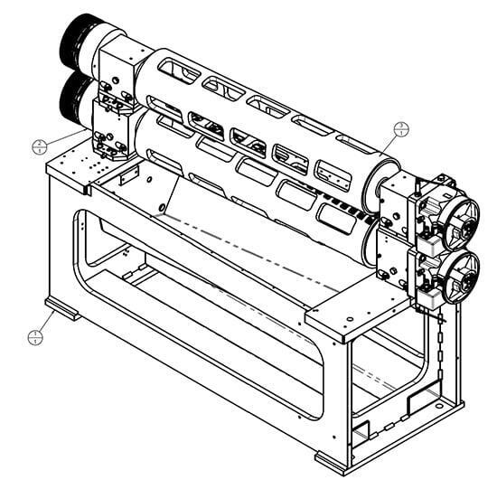
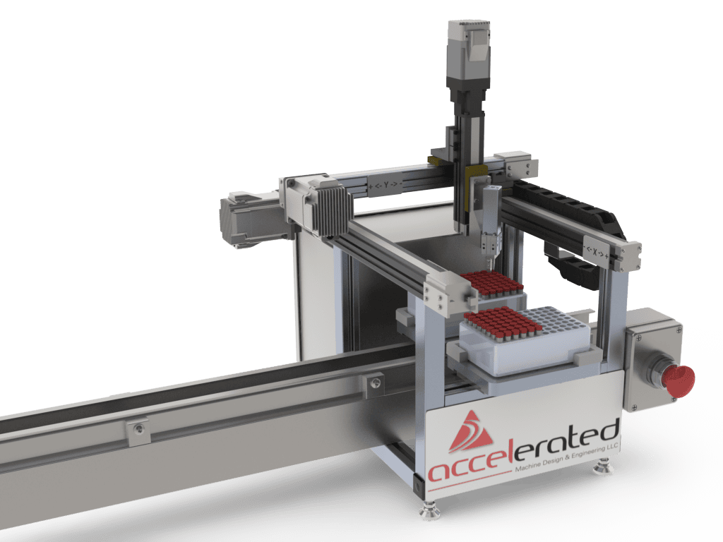
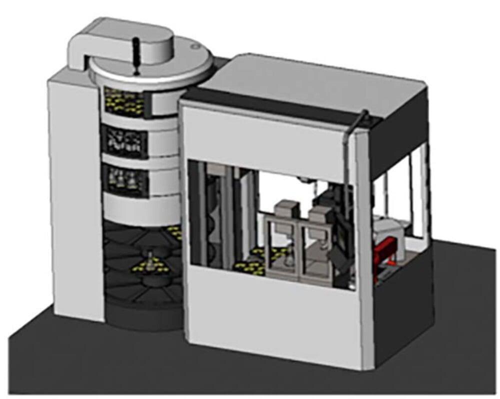
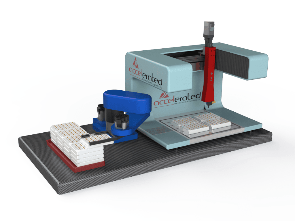
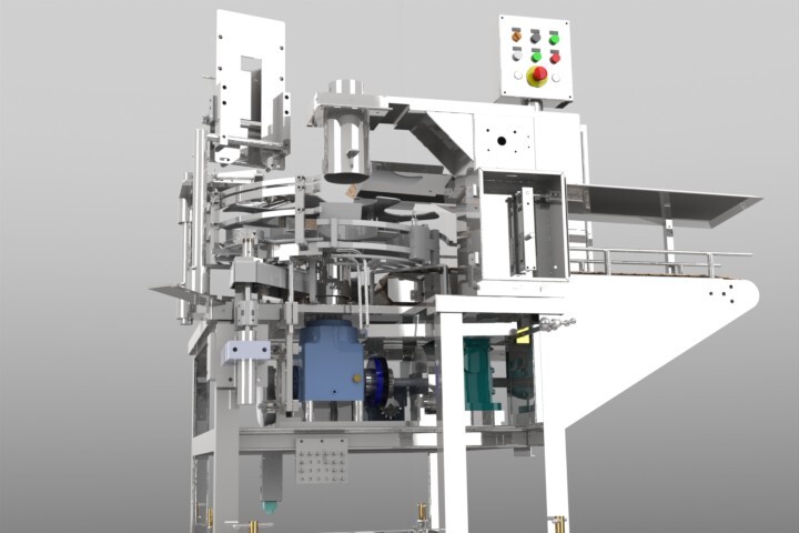
Deep Experience in designing Machine Tools and Automation Systems
Engineering Experience That Shows in Every System We Design
Our engineering portfolio spans some of the most advanced machine tools and automated systems in the world. Our team has designed high‑performance machining platforms across nearly every major aerospace and industrial material category:
- Aluminum machining systems for high‑speed production of wing skins, spars, and stringers
- Titanium machining platforms for fighter‑jet bulkheads, landing gear components, and other high‑load structures
- Steel and cast‑iron machining systems for large diesel engines, off‑highway frames, and heavy‑duty actuators
- Carbon‑fiber machining solutions for drilling, trimming, and finishing composite airframe structures
- Large‑format machining systems for dozer blades, scraper buckets, and other high‑force earthmoving components
Every system we design is engineered for a 20‑year service life and built around the fundamentals that matter most: performance, maintainability, and long‑term reliability.
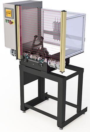
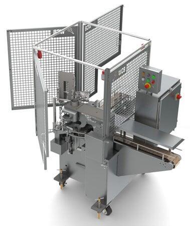
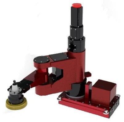
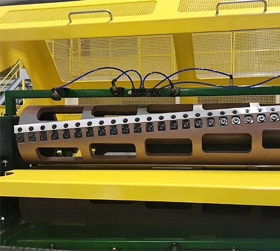
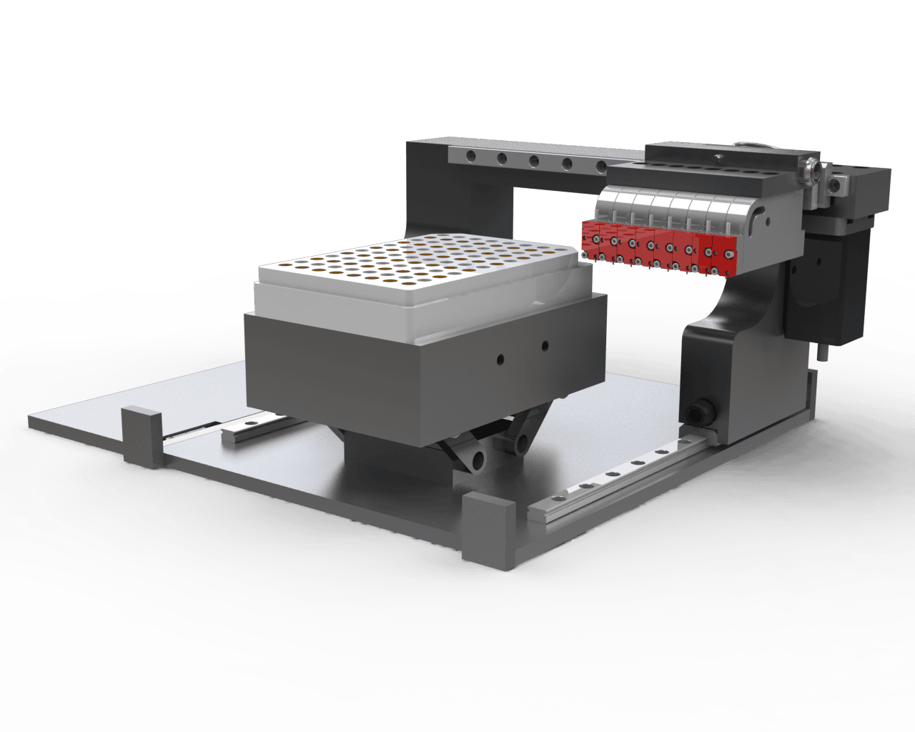
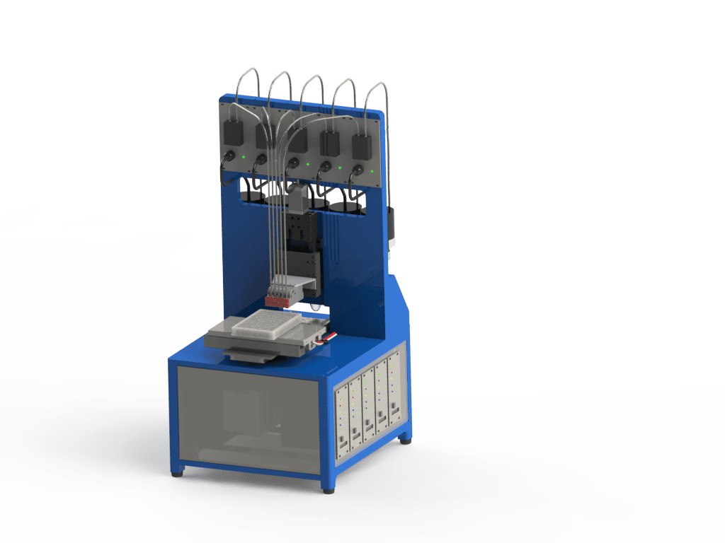
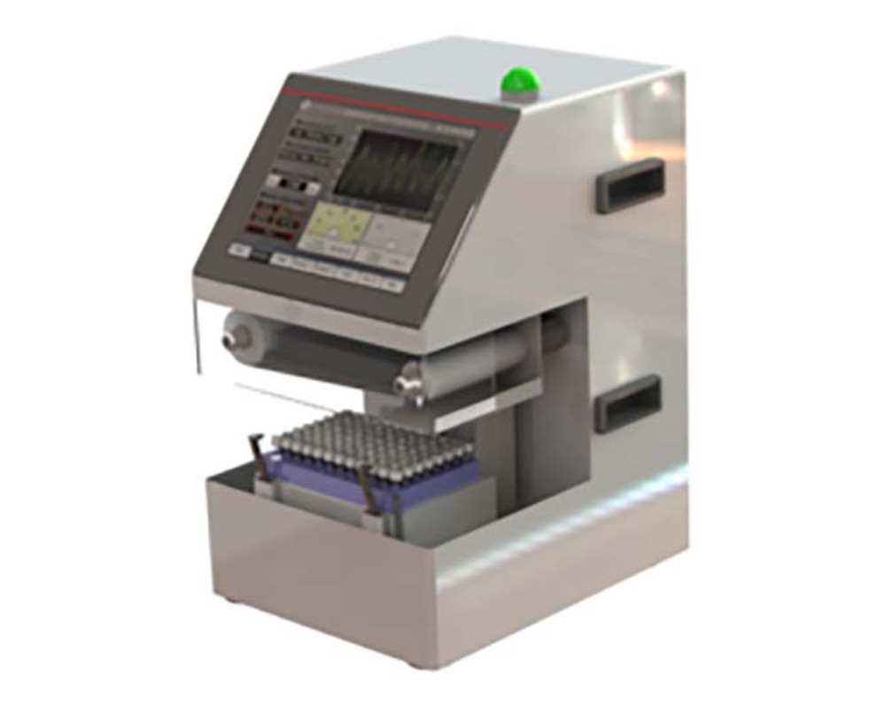
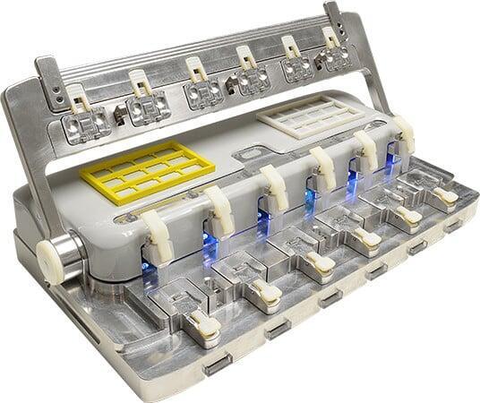
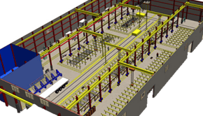
Automation Expertise for Precision Assembly and Inspection
Our automation experience includes the design of intricate assembly and inspection systems for precision‑critical products. We specialize in:
- Complex part handling
- High‑accuracy assembly processes
- Automated inspection and measurement
- Integrated motion, sensing, and control
This depth of automation experience gives us an uncommon understanding of how precision systems behave in real‑world production environments.
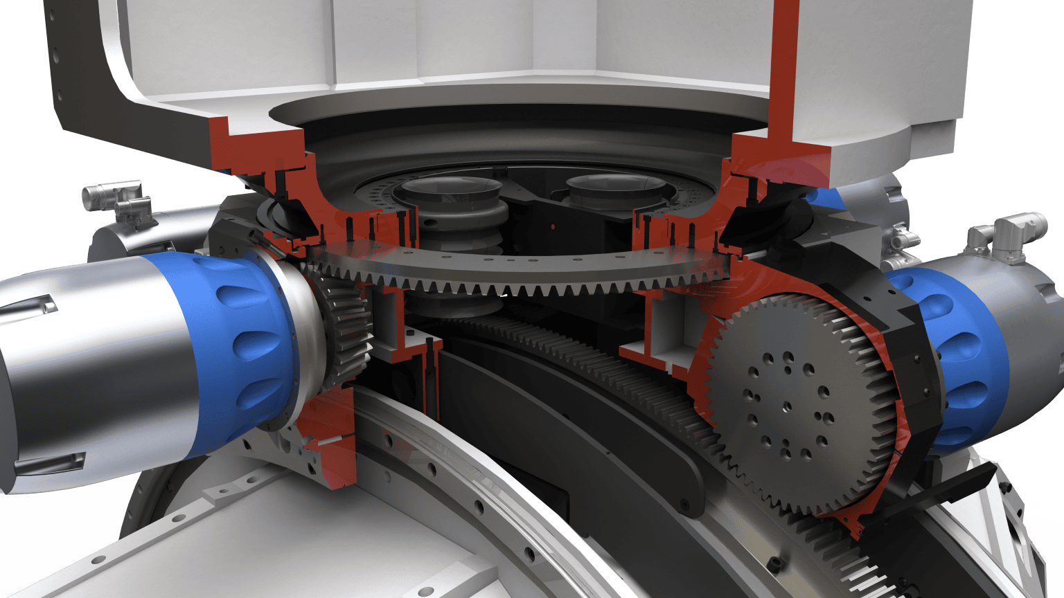
Why Our Experience Matters
The breadth of our machine tool and automation background directly strengthens our precision engineering services. It allows us to design instruments and systems that are:
- Accurate
- Precise
- Repeatable
- Robust under demanding conditions
This foundation is what enables us to deliver exceptional actuation design, high‑performance motion control, and engineered systems that operate reliably in the most challenging environments.
The Accelerated approach to Product Development
TRL, MRL, Scrum, Systems Engineering, Phase Gates, and a million more buzzwords. Product development has no shortage of frameworks promising faster results. At AMD&E we cut through the acronyms. Our approach keeps things simple, focuses on what actually matters, and delivers real, measurable results. Check back periodically for case studies that demonstrate the Accelerated approach to Product Development
The Accelerated approach to Machine Design
Great machine design starts with what works in the real world, not just in CAD. No matter how compelling a rendering looks, a successful machine is built on rigorous engineering and proven performance.
Our design engineering services ensure every machine is engineered to function from day one, and until the end of life. Structures are optimized for strength and longevity. Thermal systems are balanced for reliable operation. Electrical systems are properly grounded and compliant. Precise tolerance stack‑ups confirm that every component assembles correctly and performs as intended.
But performance alone isn’t enough. Great machine design engineering also means designing for the people who use the equipment. Ergonomics reduce fatigue and improve safety. Intuitive user interfaces increase efficiency and minimize training time. Throughput is engineered into the machine so it consistently delivers the output it was designed to produce.
None of this happens by accident. It takes experienced machine design engineers who follow a disciplined development process, while still applying creativity to solve complex problems. The result is custom machine solutions that are not only engineered correctly, but proven, reliable, and a pleasure to use.
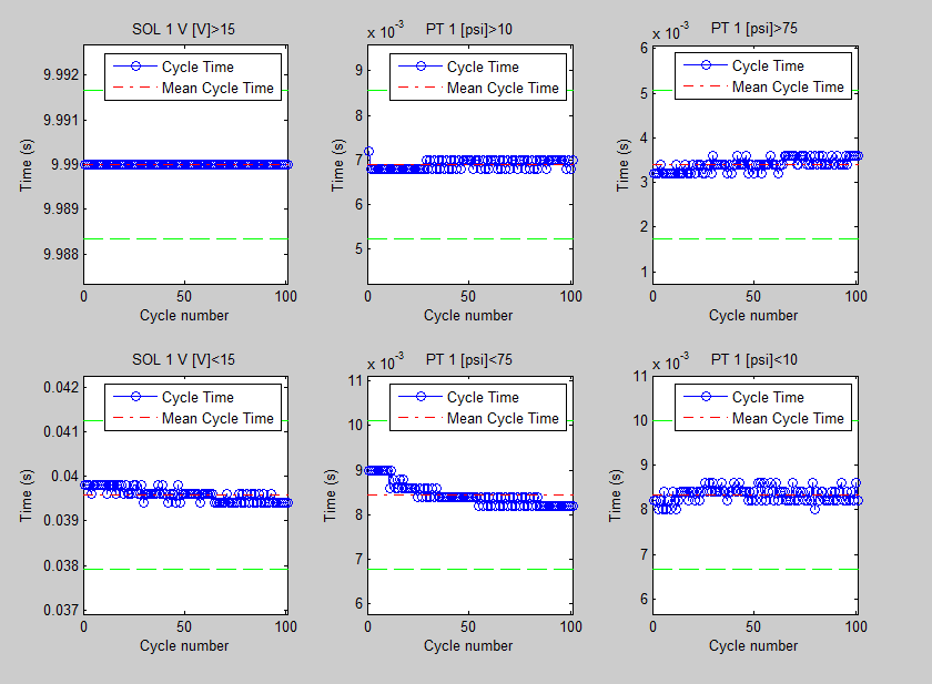
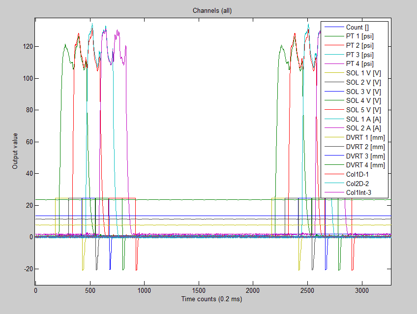
System Modeling
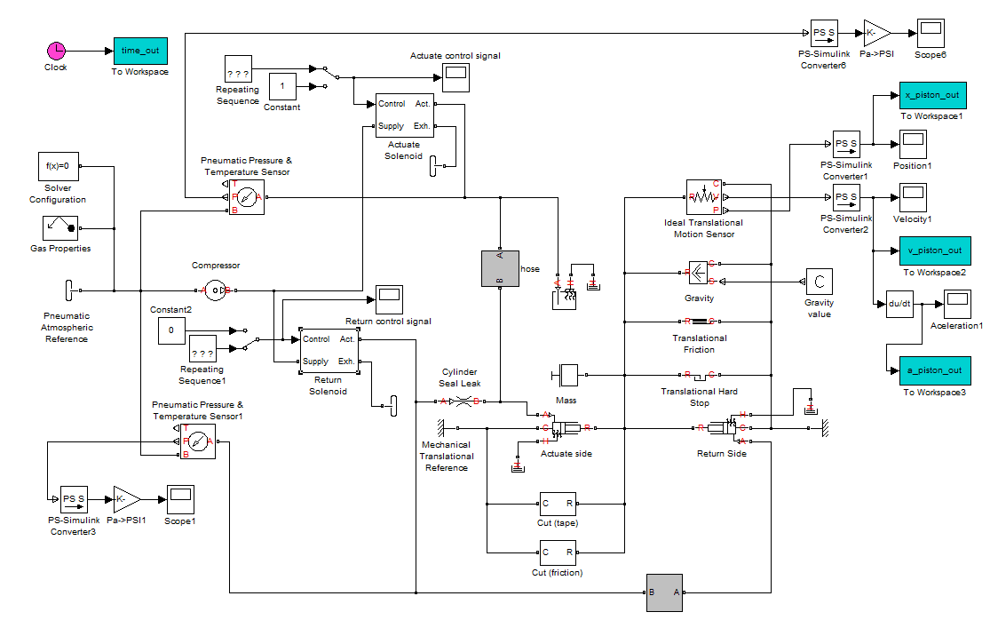
Our team uses system modeling to understand the inputs and outputs of system, and also to predict and optimize the performance of the system. The most important output of this step is to understand the important parameters and governing mechanics.
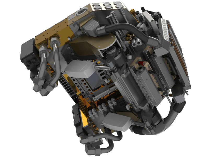
System CAD Modeling

Once the first principles are understood, a working CAD model is developed. The working model phase identifies the most important components and focuses on the functionality of the system.
This stage is critical to establish geometric relationships, critical interfaces, assembly and sub assembly hierarchy, and overall system architecture.
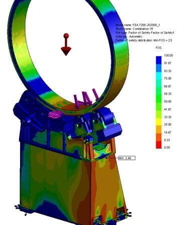
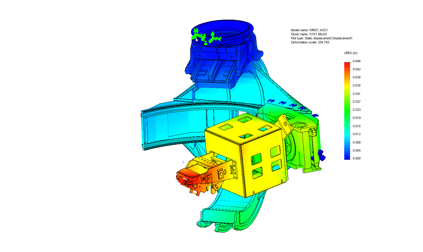
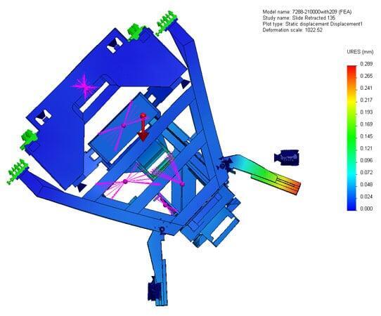
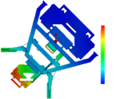
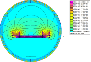
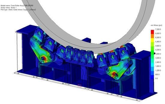
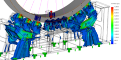
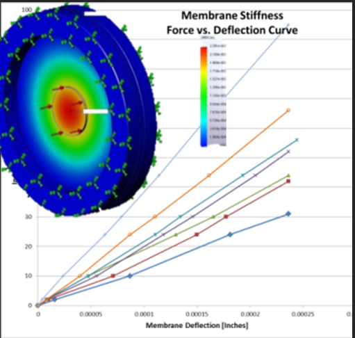
Analysis and Simulation

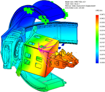
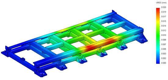
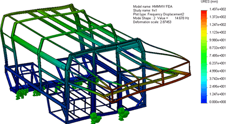
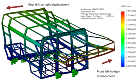
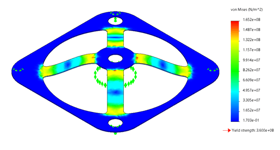
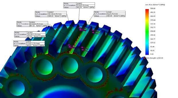
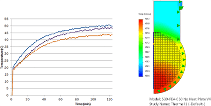
Analysis and simulation are performed concurrently with System modeling and CAD modeling. Finite Element Analysis, FEA, is used to predict stress, deflection, vibration, thermal expansion, and many other behaviors. Kinematics models are used to predict motion, stability, actuator sizing, and effects of inertia.
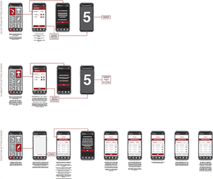
User Interfaces


Sensitivity Analysis
Sensitivity analysis is a critical step in machine design because it reveals how changes in inputs affect system performance. By evaluating how variations in loads, tolerances, material properties, temperatures, or operating conditions influence outcomes, engineers can quantify risk before it becomes a problem.
This small but deliberate step in the design engineering process helps identify weak points early, validate design margins, and prevent costly failures during assembly, commissioning, or production. When applied correctly, sensitivity analysis improves robustness, increases reliability, and ensures the machine performs as intended across real‑world operating conditions.
Detail Design
During the detail design phase, every aspect of the machine is fully defined and accounted for. A complete 3D CAD model is created for every component in the system, providing a single source of truth for design, review, and validation.
All moving components are digitally evaluated throughout their full range of motion to identify potential interferences, clearance issues, and unintended interactions early in the process. This virtual validation reduces risk, prevents rework, and ensures the machine functions as intended before anything is built.
Detailed modeling enables design for assembly, ensuring components fit correctly and can be assembled efficiently. It also supports design for maintenance, allowing engineers to visualize tool access, service clearances, installation and removal paths, and critical interfaces.
Finally, this level of detail enables design optimization for manufacturing, helping reduce complexity, improve manufacturability, and control costs—while maintaining performance and reliability.
Design for Assembly (DFA)
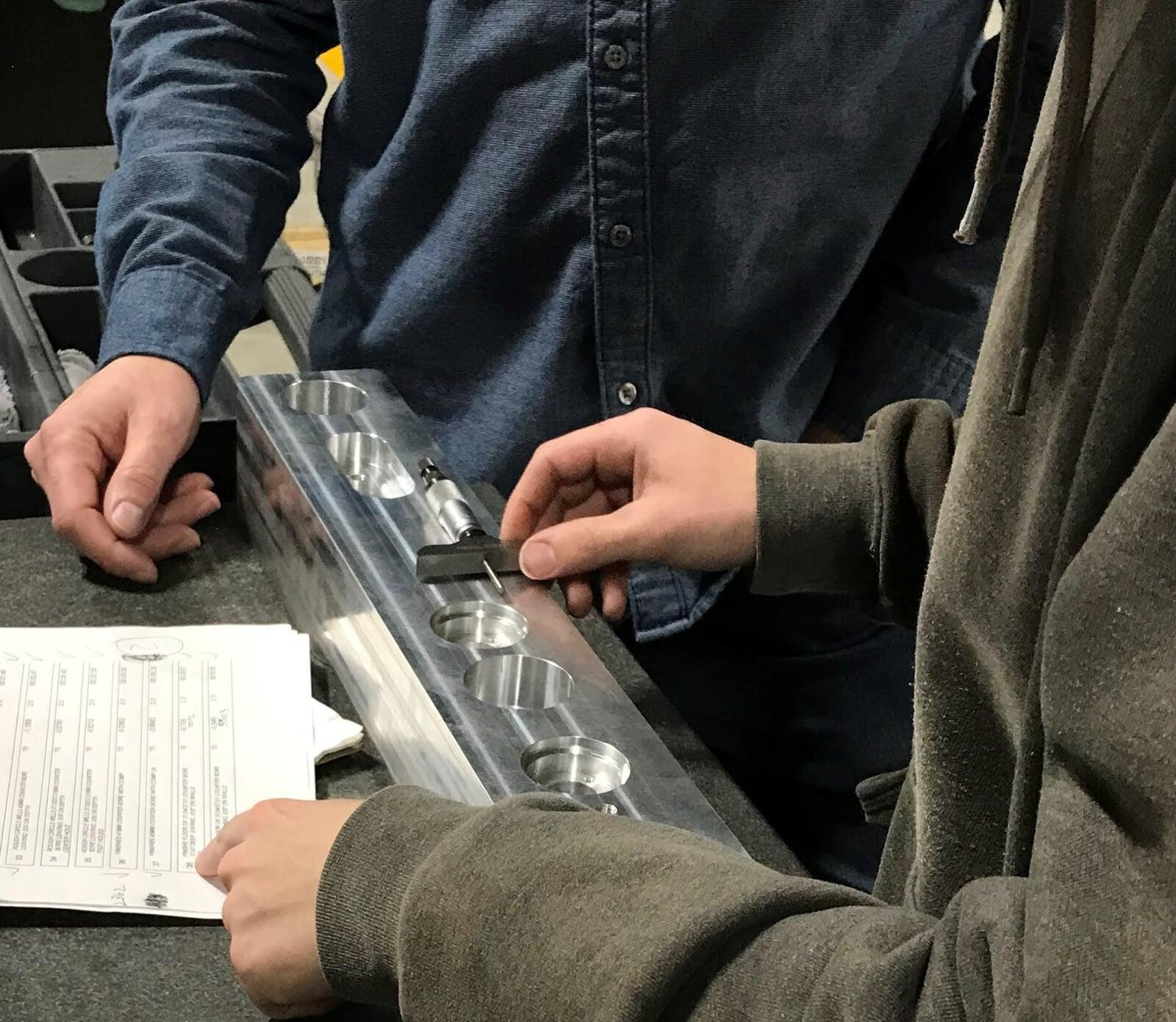
The Design for Assembly (DFA) phase ensures that every component of the machine can be efficiently and reliably assembled in the real world. Our engineering team evaluates tool and wrench access, verifies that parts can be removed for repair or replacement, and confirms that routine maintenance can be performed without obstruction.
We develop a detailed assembly plan, document all critical inspection points, and define how each inspection should be carried out. This includes creating the inspection report templates that technicians will use during build and validation.
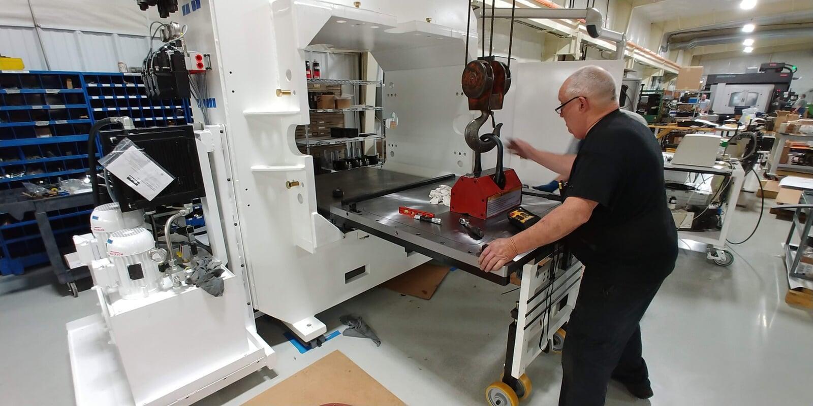
For larger systems, we also plan the safe handling of heavy components—mapping out crane picks, forklift access, lifting strategies, and alignment procedures.
This phase is essential to delivering a machine that is not only well‑designed on paper but also practical, serviceable, and safe to assemble in the field.
If you want, I can tune the tone to be more technical, more marketing‑oriented, or more concise.
Design for Manufacturing (DFM)
The Design for Manufacturing (DFM) phase focuses on ensuring that every part can be produced efficiently, repeatably, and at the required quality level. This stage requires close collaboration with the manufacturing team so that design intent aligns with real‑world production capabilities.
During DFM, component geometry is refined and optimized for the specific manufacturing processes that will be used—whether fabrication, welding, forging, casting, CNC machining, injection molding, or other methods. This includes evaluating tolerances, material selections, part orientation, tool access, and opportunities to simplify or consolidate features.
The output of this phase directly informs the detailing stage. Critical manufacturing notes, process requirements, and special instructions are captured and documented on the final detail drawings to ensure that production teams have clear, unambiguous guidance.
A strong DFM process reduces manufacturing risk, shortens lead times, lowers cost, and prevents downstream issues such as rework, scrap, or assembly delays. By resolving manufacturability challenges early, the engineering team ensures that the design is not only functional on paper but also practical and economical to build at scale.
Assembly and Detail Drawings

Next is the Detailing Phase, where the machine design is translated into complete, build‑ready documentation. Assembly drawings are created for every assembly and subassembly, clearly defining how each component fits together. These drawings provide precise instructions to ensure consistent, accurate assembly on the shop floor.
Detailed part drawings are then completed for all components requiring manufacturing. Each detail drawing includes fully defined dimensions, tolerances, material specifications, finishes, and critical features required to produce the parts correctly.
This level of documentation ensures designs are communicated clearly to manufacturers, reduces ambiguity during fabrication, and supports repeatable quality during production. Proper detailing enables efficient manufacturing, smooth assembly, and confidence that the finished machine matches the original design intent.
Engineering Specialties
Mechanical design and engineering are core strengths of our company. Our team provides a full range of analytical and engineering services, including Finite Element Analysis (FEA), Computational Fluid Dynamics (CFD), kinematic analysis, and GD&T development. These tools allow us to solve complex mechanical challenges and ensure that every design performs reliably under real‑world conditions.
We apply these capabilities across a wide range of engineering tasks: machine design, actuator and drive system sizing, structural and deflection analysis, and stress, strain, fatigue evaluation, and many other applications. Our team also supports critical system‑level decisions such as chiller and pump sizing, hydraulic system design, and lubrication system development for high‑duty machinery.
Our mechanical design services cover the full design lifecycle—from concept through production. This includes 3D modeling, machine and product design, detailed 2D drawings, and complete bills of materials. Every deliverable is created with precision, manufacturability, and long‑term serviceability in mind.
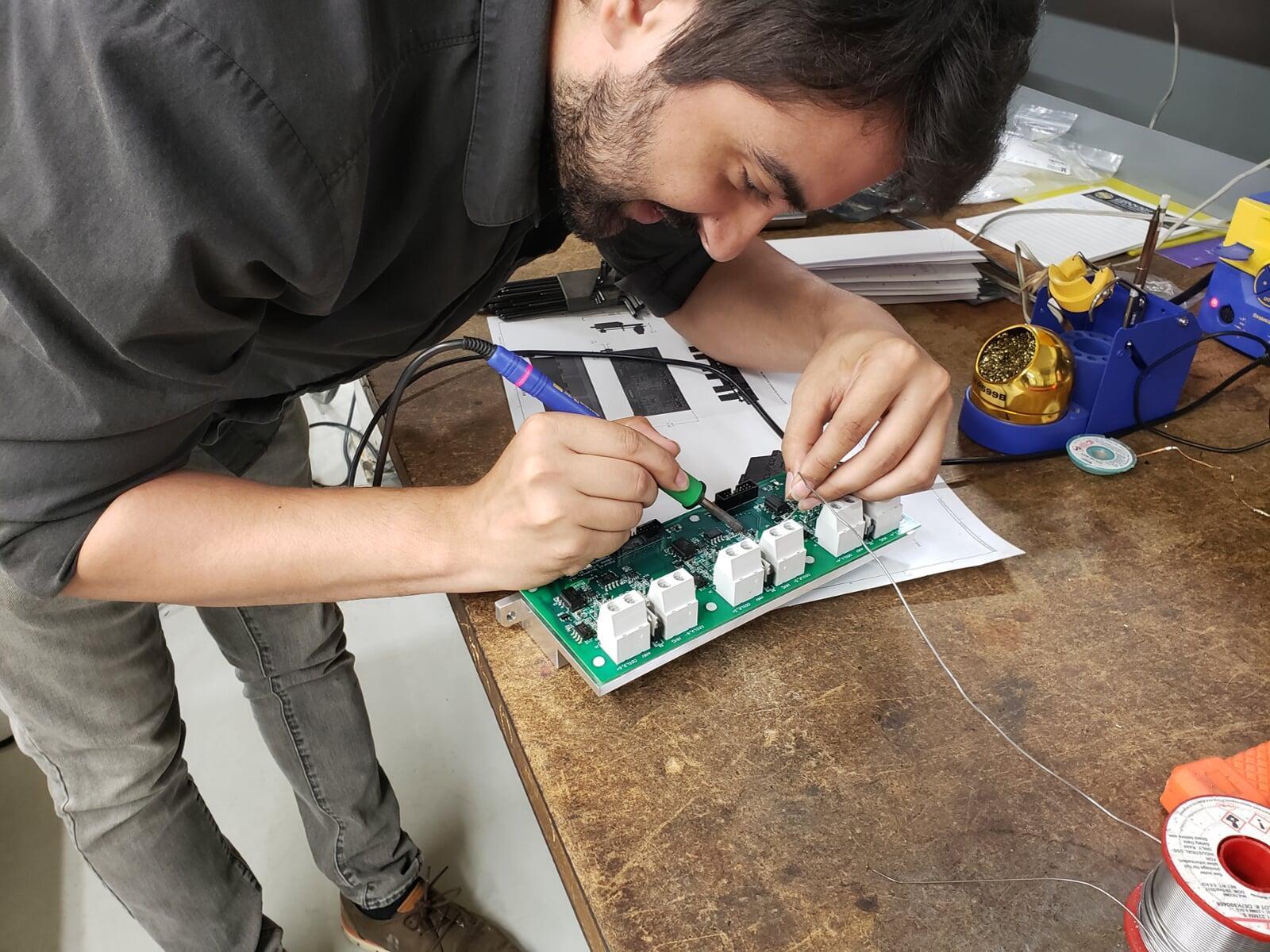
Electrical and hardware engineering are essential components of the solutions we deliver. Our team designs robust power systems for machines and automated equipment, ensuring safe, reliable, and efficient operation. We also develop complete control system architectures, from sensor integration to actuator control and system‑level logic.
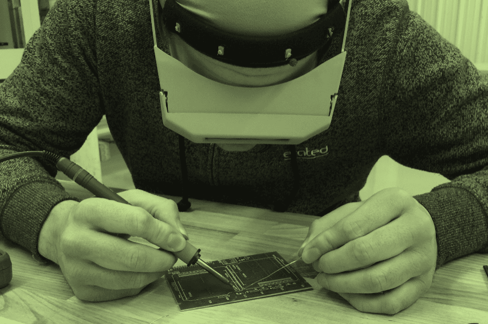
Our capabilities include detailed circuit design, PCB layout, and hardware development for both simple and highly integrated systems. Whether supporting a new machine build or upgrading an existing platform, we create electrical and hardware solutions that are engineered for performance, manufacturability, and long‑term serviceability.
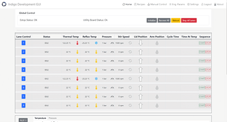
Our software and firmware engineering team develops the embedded intelligence that drives modern machines, automation equipment, and engineered products. We create reliable, real‑time code that manages motion, coordinates sensors and actuators, and ensures deterministic system behavior in demanding environments.
We work across microcontrollers, PLCs, industrial PCs, and custom hardware platforms, integrating closely with mechanical, electrical, and controls engineering teams so that software performance aligns with the full system design.
Most importantly, we deliver complete, production‑ready software assets to our customers. These deliverables include:
- Finished ladder logic and PLC programs
- Fully compiled and validated firmware
- Completed HMI screens and operator interfaces
- Finished GUIs and web‑based interfaces
- Configured and deployed databases
- Data‑logging, communication, and diagnostic modules
- Documentation packages, version control structures, and release notes
Every deliverable is built to be maintainable, testable, and ready for deployment—ensuring your machine or product performs exactly as intended from day one.
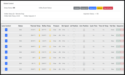
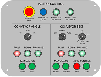
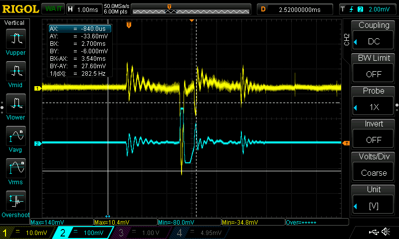
Our Automation and Controls Engineering team delivers the systems intelligence that makes machines operate safely, efficiently, and predictably. While this discipline overlaps with electrical hardware design and software engineering, it focuses specifically on the control logic, industrial communication, and motion technologies that bring complex equipment to life.
We develop and implement PLC logic, configure industrial networks, and integrate sensors, instrumentation, and safety systems into a cohesive control architecture. Our engineers specialize in servo and motion control setup and tuning, hydraulic system tuning, and the configuration of drives, valves, and actuators to achieve precise, repeatable machine performance.
Beyond design, we support full system startup and optimization. This includes commissioning equipment, validating control sequences, troubleshooting field issues, and refining performance to meet cycle‑time, accuracy, and reliability targets. The result is a fully integrated control system that is stable, maintainable, and ready for production environments.
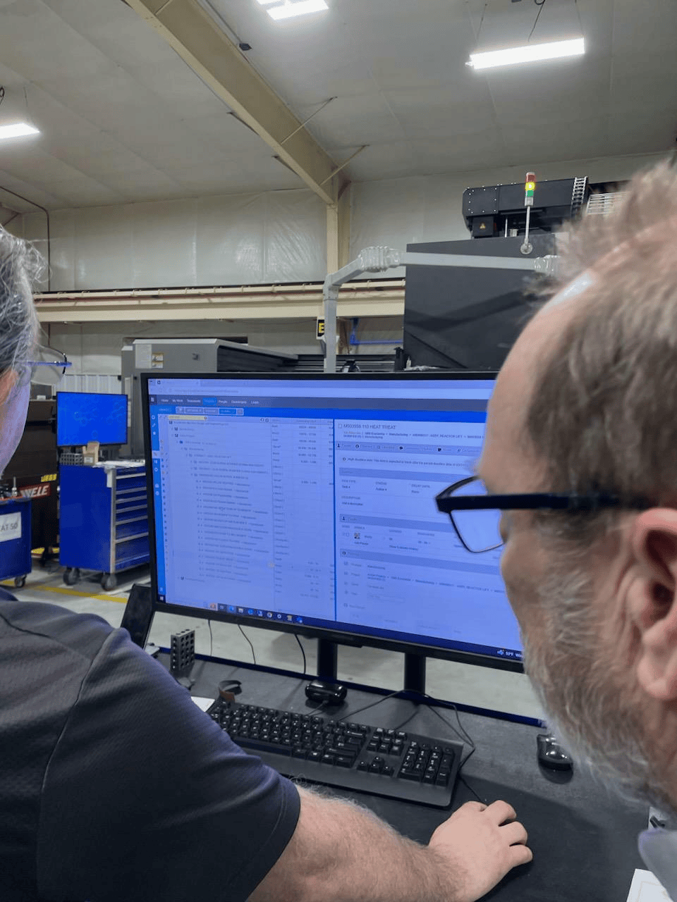
Our Manufacturing Engineering team ensures that every design can be produced efficiently, repeatably, and at the highest level of quality. We bridge the gap between engineering and the shop floor by developing robust manufacturing plans, reviewing blueprints for clarity and manufacturability, and selecting the right tools, fixtures, and processes for each part or assembly.
We provide full CAM programming support, CNC machine planning, and fixture and tool design to ensure that machining operations are optimized for accuracy, cycle time, and cost. Our engineers also lead quality planning efforts, defining inspection methods, creating inspection reports, and establishing the controls needed to maintain consistent production quality.
Beyond planning and documentation, we focus on improving real‑world performance. This includes analyzing uptime, optimizing OEE, refining machining strategies, and implementing process improvements that increase throughput and reduce variability. The result is a manufacturing process that is stable, efficient, and aligned with the technical and commercial goals of each project.