New Spindle Units Help Global Manufacturer Realize Productivity Gains
METAL MACHINING WORK IS ALL ABOUT high accuracy, productivity, and repeatability. These requirements and many others are factored during the machinery design stage. Through a systematic retrofit engineering process, AMD&E was able to extract significant performance improvements from an existing CNC horizontal machining center. The retrofitted machine enabled a global supplier of heavy rotating equipment to achieve higher productivity without a major capital investment for a completely new machine tool.
Challenge
BOURN & KOCH, INC. IN ROCKFORD, ILLINOIS, designs and manufactures new machine tools, including turning, grinding, and hobbing machines. The company also rebuilds machines and supplies components for its customers’ legacy machine tool products. One of Bourn & Koch’s major customers was looking to replace two spindle units on an Ingersoll Mastercenter machine with units better suited to the customer’s current production requirements. The customer — Houston, Texas-based maker of industrial rotating equipment Dresser-Rand — utilizes this CNC horizontal machining center to machine compressor housings and a family of massive castings for steam turbines.
“Accelerated has collaborated with us on a number of projects,” said Rob Muller, service manager at Bourn & Koch. “This was the most complex project to date. By combining our engineering department’s experience with gear making equipment and the Accelerated team’s experience with precision machine tools, we were able to devise an effective solution.”
Brand-new design
THE CURRENT PRODUCTION PROCESS for Dresser-Rand’s parts being machined is highly involved and time consuming. As the manufacturer’s machining needs evolved, the original spindle units proved inadequate in terms of the torque capacity and the structural demands placed upon them. Downtime resulting from poor spindle rigidity and high vibration had a ripple effect on further manufacturing processes.
“Dresser-Rand wanted a new, rugged spindle design with different gear ratios to achieve the necessary horsepower and torque,” Muller said. “Spindle design must take into consideration the required power, speed, torque, tooling system, accuracy, and life. Cost has a significant impact on the final spindle design as well.”
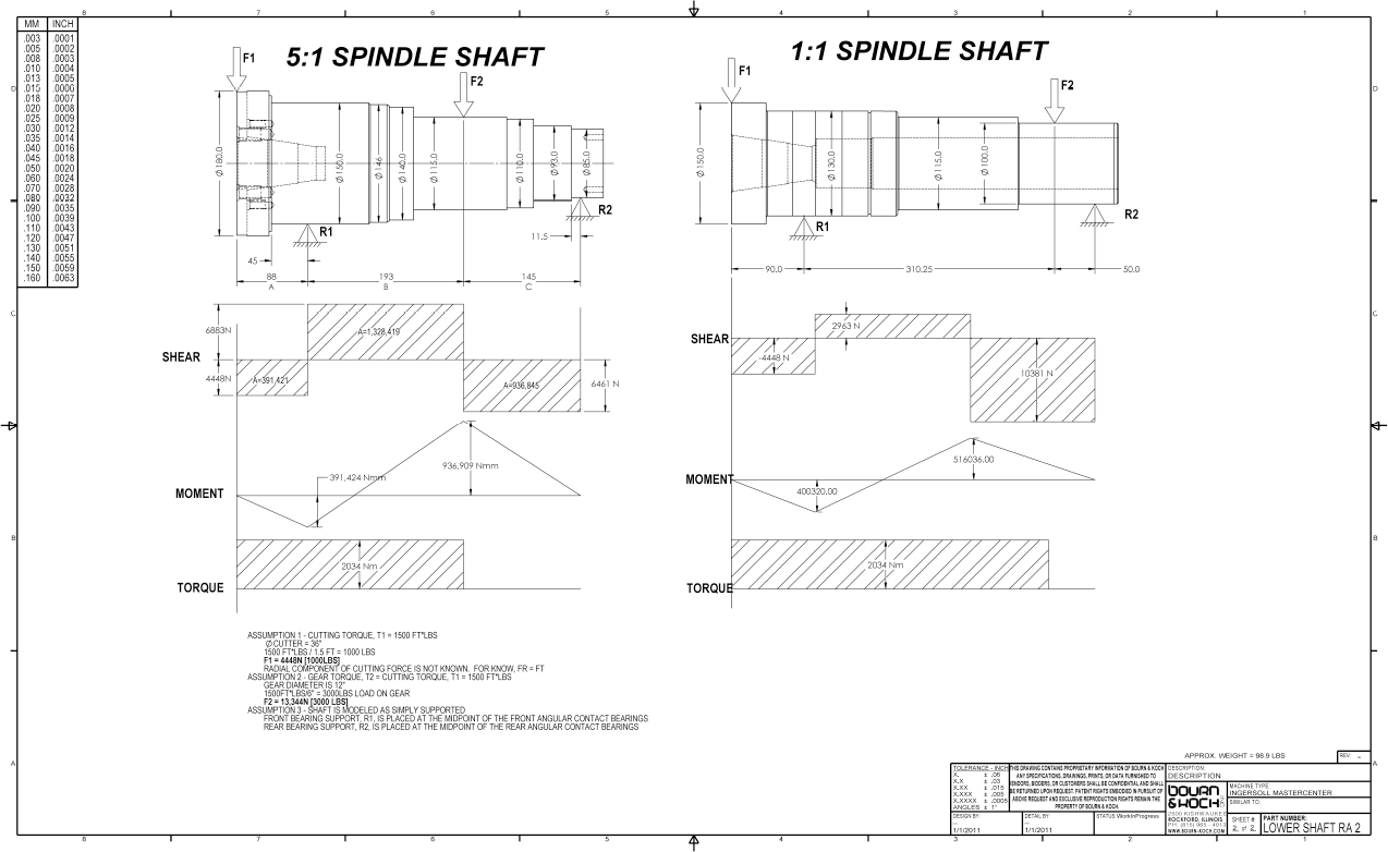
Bourn & Koch evaluated existing spindle designs as a starting point for the engineering process. To accomplish the proper surface speed, the proposed spindle units needed a 5:1 gear ratio to deliver 50 hp at 300 rpm but stay within a tightly defined space of 400mm wide x 800mm tall x 450mm deep.
“Working from our concept design, Accelerated provided the finished spindle design,“ Muller said. “Every detail, including engineering calculations, studies for spindle loads, and exacting geometric tolerances for the fit and finish of precision parts, was covered and considered. They did an exceptional job of checking and double-checking the initial calculations and complying with our engineering specifications, drawings, callout structure, and part number structure.”
 The new component and assembly designs were compared against the legacy designs to ensure acceptable ROI.
Increased performance
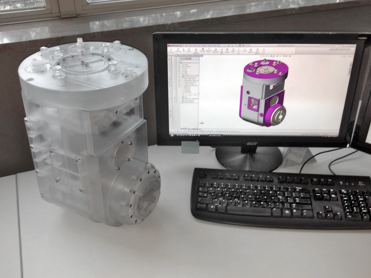
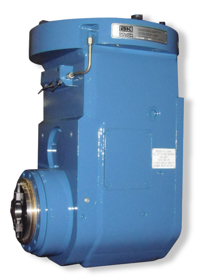
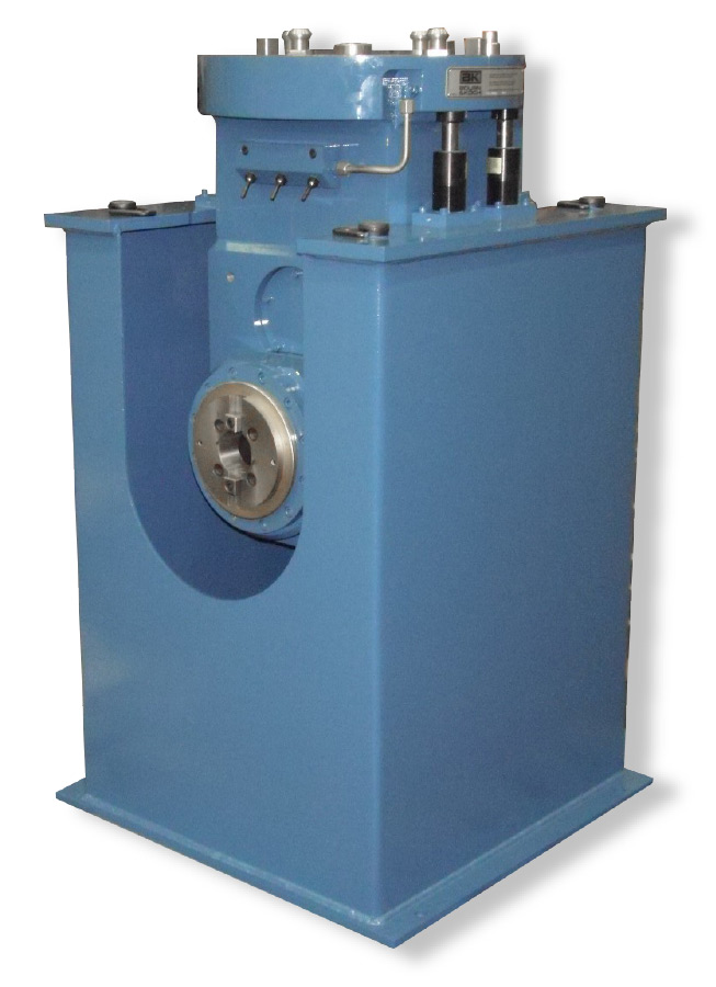
THE MASTERCENTER FEATURES INTERCHANGEABLE spindle units that perform a full range of cutting functions on the cast iron and steel alloy workpieces. The diameter of Dresser-Rand’s workpieces ranges from 1 to 3.5 meters. Flat parts can be up to 5 meters in length. Composed of a rotating section, a tool retention section, and a spindle support section, the spindle units of the Mastercenter attach directly to a gearless drive shaft in the spindle drive system. The spindle drive system furnishes coolant, hydraulic, electrical, and control services to the spindle unit.
Each spindle unit requires a unique configuration and gearing to suit the particular materials, tools, and cutting operation. For the two new units, the machine must reach deep into narrow slots and make right-angle cuts near the bottom of the part. High spindle rigidity, minimized rotation vibration, and low thermal distortion enable heavy cutting and satisfactory finish cutting and grinding performance.
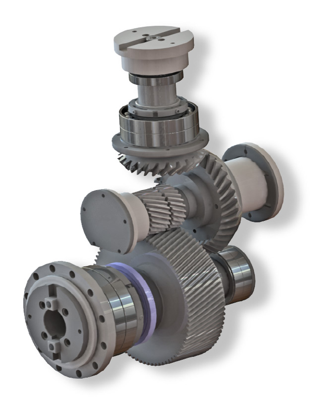 Structural engineering, gear analysis, and drive engineering were performed to optimize the system.
The original spindles — in this case, straight and right-angle variants — were engineered to hold traditional face mill and smaller cutting tools approximately 4 to 12 inches in diameter. With a 1:1 gear ratio, the original spindle units transferred 50 hp at 1,500 rpm output speed. A change to larger slotting tools (up to 38 inches in diameter) started to cause performance issues.
To maintain the same cutting speed as the small tools, the larger slotting tools have to operate at a lower rotational speed. This lower rotational speed, however, was outside of the optimal operating window for the drive motor, which restricts the machine to making lighter cuts.
Reduced maintenance
ONE BYPRODUCT OF A LOW ROTATIONAL SPEED is high vibration in the spindle unit gear train. High vibration levels not only shorten spindle life and inhibit consistent machining accuracy but also exert heavy wear on the spindle face keys. As a result, Dresser-Rand was forced to repair the original spindle units every four years. Because the 5:1 ratio in the new spindle units raises the input speed by a factor of five, vibration levels in the gear train are significantly lower, resulting in less frequent required maintenance.
Precision first
AMD&E DESIGNED THE SPINDLE UNITS for stable operation, with minimal changes in bearing preload and gear alignment during operation. Particular focus was applied to the dynamic balance of each rotating component. Fine dynamic balancing and stable spindle operation throughout the spindle speed range improves the achievable accuracy and precision, extends tool life, and enables fine surface finishes to be created.
Fit and finish
AMONG THE BIGGEST CHALLENGES for the Accelerated team was specifying the optimal fit and finish of approximately 80 parts (for each spindle unit), which would be sourced from seven suppliers.
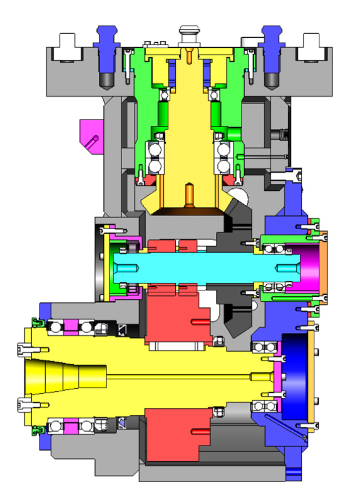
A thorough detail design process (including GD&T and tolerance stack-up analysis) and a rigorous and iterative checking process ensured proper fit and finish.
“As with any design and subsequent assembly process, it was critical that each part mate correctly,” the Accelerated team said. “There were close fits between parts in some cases, to get everything packaged within the housing. A few of the parts were old Ingersoll parts that we basically re-engineered in order to update the part information. We had to be very specific on materials and heat treatments and very accurate in how all the geometric tolerances were applied.”
Deeper reach
ALTHOUGH THE SPINDLE UNIT DESIGN emphasized higher productivity, higher torque, and reduced maintenance, the engineers quickly realized that the new design could offer even more performance enhancements. Increasing the distance from the mounting surface to the centerline of the cutter allows the machine to reach deeper into the internal cavities of turbine cases and take deeper cuts.
Ongoing support
FOLLOW-UP ENGINEERING SUPPORT to Bourn & Koch throughout the manufacturing and assembly process has been critical to this project’s success. Bourn & Koch manufactured parts at its Rockford plant and has contracted with other manufacturers on certain components. The Accelerated team prepared a complete book of detailed manufacturing drawings with a bill of materials, material identifications, and processing requirements. Assembly layouts for each spindle unit gave the assembly floor instructions on fitting the parts together.
“Bringing Accelerated’s engineering into our company made our life easier,” Muller said. “They were always available by phone or in person, either at our facility or traveling to the end-customer site. Every step of the design and engineering was well communicated to avoid any possible delay. Accelerated kept the project on schedule and within cost.”